How can we help you today?
NZ-Cascade
Cascade Load-Side Piping

Notes:
- All units must be the same size and configuration. For Example a 22kW or the model number ends in RB.
- A compact unit maybe used but it recommended to be used as the Master unit.
- 3 Units are shown but 2 units may be used as well.
- Check valves are needed at each unit on the load side. Other circuits might also need check valves depending on configuration.
Cascade Source-Side Piping
Notes:
- The Source side is independant from the load side and when piped in parallel check valves or 2-way valves are required to prevent flow from going through the unit when it is off.
- External individual pumps may be used (check valves required), UPMXL with PWM control signal. See external pump wiring diagram.
- 2-Way Control Valve with 2-10Vdc input signal. Connected to AO6 in Netzero.
Cascade Wiring

Wiring Notes:
- Cable: Use 3 conductor cable with foil shield and braided drain wire.
- Conductors: Stranded wire 18-22 AWG.
- Shield: Connect shield drain wire to PE (GND) terminal at DO17.
- Do Not Run Control wire parallel to Power wiring.
- Before any configuration ensure pLAN (J14) connectors are disconnected. If you do not disconnect pLAN cable before configuration it could lead to malfunctions and damage to components in the heat pumps.
- Input/Output Wiring connects to Master Unit.
- Disconnect pLAN (J14) cable if software update is to performed.
Cascade Programming
Before Programming:
- Confirm all “Main” pCOOEM controllers in each unit are the same type; pCOOEM+ or pCOOEM+HS or pCOOEM+SK. Not sure how to tell the difference see pictures here.
- Confirm all “Main” pCOOEM Controllers have the same version of software installed. Check; User Menu > Information > Version Screen. The first line (Ver.) is the version of Software installed. If they are different, update all units to the same version. Can use Quick Save function to copy the software from one unit to another. This feature only works with if you have a USB port (pCOOEM+ or pCOOEM+HS).

Checklist before Starting:
- Wire 3 (18‐22AWG) conductor cable with shield between units (J14 pLAN).
- Cable does not run near or parallel to any high voltage power wiring.
- Leave connector disconnected until setup complete.
- Check 3 settings
- Turn off unit (User Menu > On/Off Menu > State: OFF)
- Verify Source is setup correctly (Installer Menu > Installation > Source)
- Set Protections (Installer Menu > Installation > Protections)
- Set Brine Protection (MaxT, MinT and MinP)
- Set Production Protection (MinT, MinP and Anti frost “unchecked”)
- Other settings can be changed after cascade setup.
Step 1 – Enable Cascade Mode in each unit
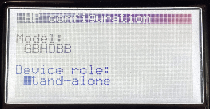
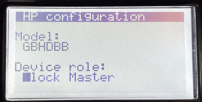
- Confirm Heat Pump Model is same as fabrication number (Installer > Installation > Heat Pump Model) all letters should the same in every unit except 2nd letter may be different ex. GCHCAB.
- Make address changes (Installer Menu > Installation > Heat Pump Model: Set to Block Master or Block Slave).
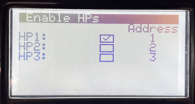
- Next screen “Enable HPs”; check box for each unit you plan on connecting.
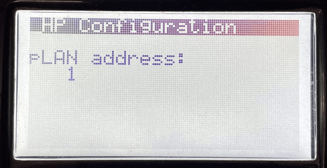
- Next screen, “HP Configuration”; Change pLAN address based on table.
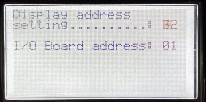
- Set Display + I/O Control addresses equal to 33 when summed. Press [↑]+[↵]+[↓] at the same time for 3 seconds to access menu. (Master will be set correctly by default)
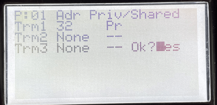
- Change terminal address based on unit, see table and “Pr” private and change Ok?No to Ok?Yes.
| TABLE 1 | Master HP1 |
Slave HP2 |
Slave HP3 |
| Control Address | 1 | 2 | 3 |
| Display Address | 32 | 31 | 30 |
Step 2 – Connect Units
- Power OFF units (Control & Inverter) 2‐3 mins
- Connect pLAN cable in each unit
- Power units ON
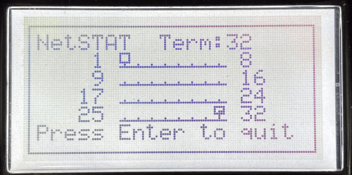
Step 3 – Verify addresses
- Confirm all addresses of units are visible and functional. Press [↑]+[↵]+[↓] at the same time for 6 seconds to access screen showing netSTAT network. Or (User Menu > On/Off; next screen will show netstat network. White boxes are the address of controller (1, 2, 3) and box with black are display addresses (30, 31, 32).
- DHW Cascade (Installer Menu > Installation > Services Setup > DHW > DHW Cascade) Check box if it has an independent DHW tank from block master.